Engineering & feasibility review
The approved drawing is reviewed for alloy, geometry, wall and bottom requirements, critical dimensions, secondary operations and production quantity.

Precision impact extrusion & cold forging
Backward impact extrusion transforms prepared aluminium and copper material into deep, seamless components with an integral base, efficient metal utilisation and drawing-led dimensional control.
Submit a forming RFQProduct scope
Drag the curved gallery to review six current product families. Final geometry, material condition and dimensional requirements are confirmed through drawing review and component development.
Seamless aluminium cases with controlled walls, an integral base and drawing-defined critical dimensions.
Detailed product capabilities
Review the manufacturing route, engineering inputs and qualified capability statements for three core aluminium product families.
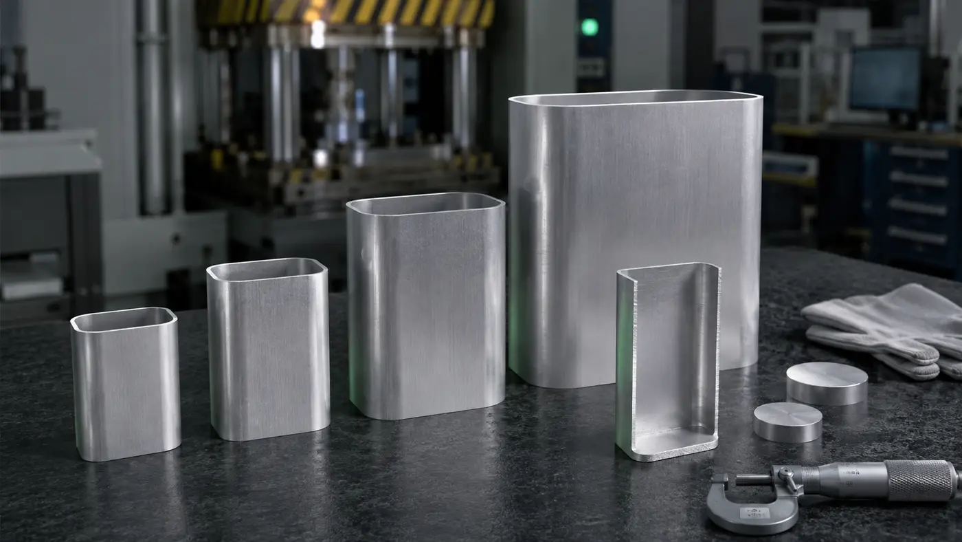 01 / CELL HARDWARE
Seamless walls, integral closed bases and drawing-defined critical dimensions.
View capability →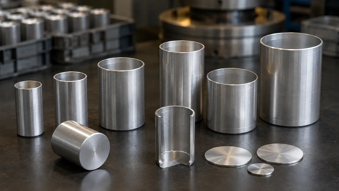 02 / ELECTRICAL COMPONENTS
Deep open-top cans produced with controlled wall and bottom distribution.
View capability →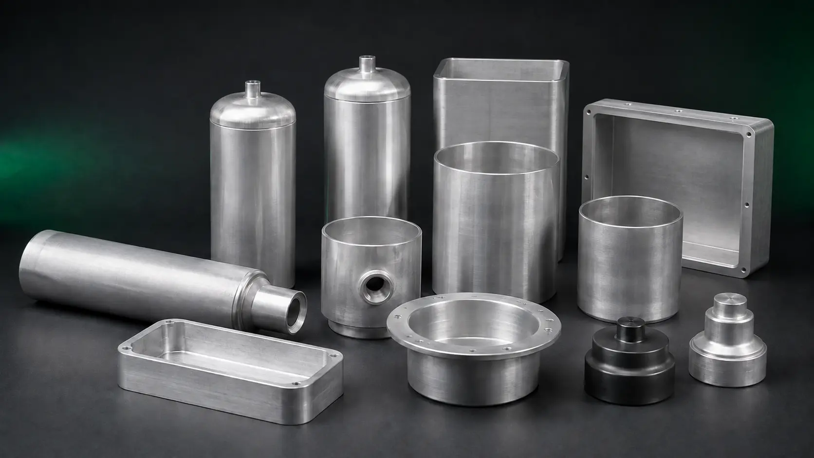 03 / CUSTOM GEOMETRIES
Round, rectangular, flanged and deep-housing geometries developed to drawings.
View capability →Controlled manufacturing route
The process is planned around the drawing and alloy response. Each operation has a defined purpose; secondary operations are included only when the final geometry or interface requires them.
Punch advances ↓ / Material flows ↑ around the punch
The approved drawing is reviewed for alloy, geometry, wall and bottom requirements, critical dimensions, secondary operations and production quantity.
The specified non-ferrous material, slug volume, surface condition and lubrication route are matched to the component and tooling plan.
Punch, die and ejection elements are aligned; clearances, stroke and forming-force limits are established before controlled trial production.
The punch displaces metal backward through the punch-to-die clearance, creating a deep seamless wall and integral closed base under compressive flow.
Trimming, sizing, piercing, forming or machining are applied only where required by the drawing and functional interface.
Formed components are washed to remove process residues before dimensional inspection or the next specified operation.
Drawing-defined characteristics, wall and bottom distribution, length, diameters and surface condition are checked before release.
Critical process controls
Process settings and inspection points are established for the component rather than applied as a generic recipe.
Material grade and condition
Slug volume and surface condition
Lubrication route
Punch-to-die clearance and alignment
Press force, stroke and ejection
Wall and bottom distribution
Secondary-operation allowance
Agreed dimensional inspection plan
Tolerance statement
A capability of ±0.05 mm can be applied to selected critical dimensions confirmed during engineering review and quotation. It should not be interpreted as a universal tolerance across every feature of every component.
Achievable tolerances and the maximum formed length depend on alloy and material condition, component geometry, diameter-to-length ratio, wall and bottom thickness, tooling, secondary operations and the agreed inspection method.Component development